
How to design a clock divide-by-3 circuit with 50% duty cycle?
 This content is from the following blog:
vlsiwizard.blogspot.com/2008/01/design-clock-divide-by-3-circuit-with.html
The basic insight was to notice that if you are doing a divide by 3 and want to keep the duty cycle at 50% you have to use the falling edge of the clock as well.
The trick is how to come up with a minimal design, implementing as little as possible flip-flops, logic and guaranteeing glitch free divided clock.
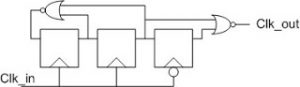
Most solutions people come up for this, utilized 4 or 5 flip flops plus a lot more logic than I believe is necessary. The solution, which I believe is minimal requires 3 flops – two working on the rising edge of the clock and generating a count-to-3 counter and an additional flop working on the falling edge of the clock.
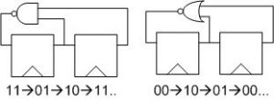
A count-to-3 counter can be achieved with 2 flops and a NOR or a NAND gate only, as depicted below. These counters are also very robust and do not have a “stuck state”.
The idea now is to use the falling edge of the clock to sample one of the counter bits and generate simply a delayed version of it.
We will then use some more logic (preferably as little as possible) to combine the rising edge bits and falling edge bit in a way that will generate a divide by 3 output (with respect to out incoming clock).
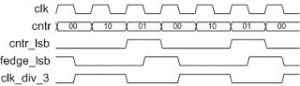
The easiest way (IMHO) to actually solve this, is by drawing the wave forms and simply playing around. Here is what I came up with:
and here is also the wave form diagram that describes the operation of the circuit, I guess it is self-explanatory.
One more interesting point about this implementation is that it does not require reset! The circuit will wake up in some state and will arrive a steady state operation that will generate a divide by 3 clock on its own.